Leading professionals in the tool/mold manufacturing industry.
Kenvox maintains strict quality control, deadlines, and voice activities with internal staff.
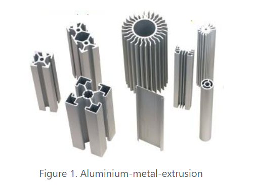
Metal Extrusion is a metal-forming manufacturing process in which a cylindrical billet inside a closed cavity is forced to flow through a die of the desired cross-section. These fixed cross-sectional profile extruded parts are called “Extrudates” and are pushed out using either a mechanical or hydraulic press. The process, patented by Joseph Bramah, was first used to extrude lead pipes by Thomas Burr
.
The most commonly extruded materials are Aluminium, Copper, Steel, Magnesium, and Lead. Plastics and ceramics are also extruded extensively but not discussed in this article.
· Factors that affect the quality of extrusion are die design, extrusion ratio, billet temperature, lubrication, and extrusion speed. Check out the detailed design guide for metal extrusion, “How to design parts for direct metal extrusion”, to understand the 5 key design variables of metal extrusion and design for manufacture (DFM) extrusion design tips.
· Like any other metal-forming process, it can be either hot or cold. However, the process is generally carried out at elevated temperatures to reduce the extrusion force and improve the material’s ductility.
· Low cost due to reduced raw material wastage and high production rate
· Brittle material can be deformed without a tear as it only exerts compressive and shear forces in the stock part
· Parts that are formed have an excellent surface finish which minimizes post-processing machining
· Metal extrusion tends to produce a favourable elongated grain structure in the direction of the material.
· The minimum wall thickness of ~1mm (aluminium) to ~3mm (steel) could be achieved.
Metal extrusion can be subdivided and grouped into the following categories depending on the direction of extrusion flow, the medium used to apply force, working temperature, etc.
· Direct Extrusion
· Indirect Extrusion
· Hydrostatic Extrusion
· Lateral or Vertical Extrusion
· Hot extrusion
· Cold Extrusion
· Impact Extrusion
Direct Extrusion, sometimes called Forward Extrusion, is the most common type of extrusion. As shown in the figure below, the process begins by loading a heated billet (only for hot extrusion, discussed later) into a press cavity container where a dummy block is placed behind it. Then the mechanical or hydraulic ram presses on the material to push it out through the die. Then, while still hot, the part is stretched to straighten. This process is beautifully animated by Core Materials.
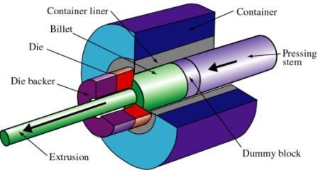
Figure 2 – Direct extrusion (source: Kalpakjian & Schmid)
Under direct extrusion, the high friction caused by steels at higher temperatures is reduced using molten glass as a lubricant while oils with graphite powder are used for lubrication for low temperatures. The dummy block protects the tip of the pressing stem (punch or ram) in hot extrusion. When the punch reaches the end of its stroke, a small portion of the billet called the “butt end” cannot be pushed through the die opening.
· No billet modification required
· It can be used for both hot and cold extrusion.
· Simple tooling compared to other extrusion processes
· High force requirement due to friction
· The butt end left inside the cavity
· The force required to push the ram changes as the punch moves
In Indirect Extrusion, the die is located at the end of the hydraulic ram and moves towards the billet inside the cavity to push the material through the die. This is illustrated in figure 2 below.
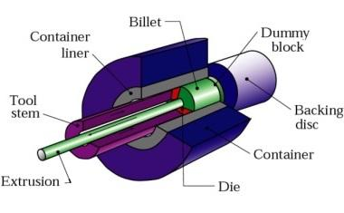
Figure 3 – In-direct extrusion (source: Kalpakjian & Schmid)
This process consumes less power due to the static billet container causing less friction on the billet. However, supporting the extruded part is difficult when the extrudate exits the die.
· Less friction and less power used
· It can be used for both hot and cold extrusion
· Simple tooling compared to other extrusion processes
· Difficult to support the extruded part
· The hollow ram limits the load applied
In hydrostatic extrusion, the chamber/ cavity is smaller than the billet and filled with hydraulic fluid, which transfers the force from the ram to the billet, as shown in figure 3. Although tri-axial forces are applied by the fluid, the pressure improves billet formability on the billet. Sealing the fluid must be considered early to avoid any leaking and reduce pressure issues.
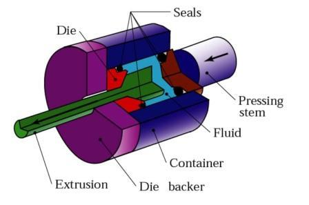
Figure 4 Hydrostatic extrusion process (Kalpakjian & Schmid)
Although the hydraulic fluid eliminates the friction between the wall and the billet by isolating them, due to the specialised equipment requirement, the high set-up time and low production rate limit its usage in the industry compared to other extrusion processes.
· Low power/force requirement due to no friction
· Fast production rates & high reduction ratios
· Lower billet temperature
· Even the flow of material due to the balanced force distribution
· Large billets and large cross-sections can be extruded
· No billet residue is left in the container
· Billets need to be prepared by tapering one end to match the die entry angle.
· Only cold extrusion is possible
· Difficult to contain the high-pressure fluid
In Lateral Extrusion, the container is in a vertical position, as shown in the image, and the die is on the side. This process is suitable for low melting point material.

Figure 5 – lateral extrusion process schematic (source : Kalpakjian & Schmid)
Impact extrusion is part of the cold extrusion category, very similar to In-direct extrusion and limited to softer metals such as Lead, Aluminium and copper. As the schematic illustrates, the punch is pushed down at high speed and has extreme force on the slug to extrude backwards. The thickness of the Extrude is a function of the clearance between the punch and the die cavity. The Extrudates are slid off the punch using a stripper plate.

Figure 6 Impact extrusion process (source: Kalpakjian & Schmid)
For impact extrusions, a mechanical press is often used, and the part is formed at high speed and over a relatively short stroke
Since the forces acting on the punch and die extremely high, tooling must have sufficient impact resistance, fatigue resistance and strength for extruding metal by the impact. Impact extrusion can be divided into the following three types by material flow.
· Forward
· Reverse
· Combination
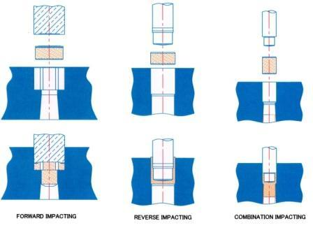
Figure 7 Types of Impact extrusion process (source : Kalpakjian & Schmid)
In forward impact extrusion, the metal flows in the same direction that the force is delivered, while it flows in the opposite direction in reverse impact extrusion. As the image shows above, the metal flows in both directions in combination.
· Raw material savings of up to 90%
· Reduced machining times by up to 75%
· Elimination of secondary machining operations
· Reduction in multi-part assemblies
· Improved mechanical properties for material strength and machining due to the cold working of the material
· Significantly reduced total part costs by up to 50%
· Hollow thin-walled tubes, closed on one end, are often produced in the manufacturing industry by backward impact extrusion.
· Produced as long as the part is symmetrical over the axis by which it is formed
· Many of the parts formed by impacting in industry, will require further manufacturing processes, such as metal forging, ironing or machining, before completion.
Depending on the material condition and process variables, extrudates can develop many defects that could affect the quality of the end product. These defects can be grouped under the following three defects.
· Surface cracking
· Piping
· Internal cracking